- 您现在的位置:买卖IC网 > Sheet目录332 > IRS2003STRPBF (International Rectifier)IC DRIVER HALF-BRIDGE 8-SOIC
IRS2003(S)PbF
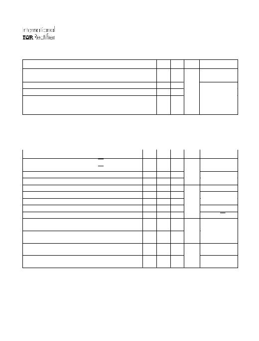
Dynamic Electrical Characteristics
V BIAS (V CC , V BS ) = 15 V, C L = 1000 pF and T A = 25 ° C unless otherwise specified.
Symbol
Definition
Min. Typ. Max. Units Test Conditions
ton
toff
tr
tf
DT
MT
Turn-on propagation delay
Turn-off propagation delay
Turn-on rise time
Turn-off fall time
Deadtime, LS turn-off to HS turn-on &
HS turn-on to LS turn-off
Delay matching, HS & LS turn-on/off
—
—
—
—
400
—
680
150
70
35
520
—
820
220
170
90
650
60
ns
V S = 0 V
V S = 200 V
Static Electrical Characteristics
V BIAS (V CC , V BS ) = 15 V and T A = 25 ° C unless otherwise specified. The V IN , V TH, and I IN parameters are referenced to
COM. The V O and I O parameters are referenced to COM and are applicable to the respective output leads: HO or LO.
Symbol
Definition
Min. Typ. Max. Units Test Conditions
V IH
V IL
V OH
V OL
I LK
I QBS
I QCC
Logic “1” (HIN) & Logic “0” ( LIN ) input voltage
Logic “0” (HIN) & Logic “1” ( LIN ) input voltage
High level output voltage, V BIAS - V O
Low level output voltage, V O
Offset supply leakage current
Quiescent V BS supply current
Quiescent V CC supply current
2.5
—
—
—
—
—
—
—
—
0.05
0.02
—
30
150
—
0.8
0.2
0.1
50
55
270
V
μ A
V CC = 10 V to 20 V
I O = 2 mA
V B = V S = 200 V
V IN = 0 V or 5 V
I IN+
I IN-
V CCUV+
V CCUV-
Logic “1” input bias current
Logic “0” input bias current
V CC supply undervoltage positive going
threshold
V CC supply undervoltage negative going
threshold
—
—
8
7.4
3
—
8.9
8.2
10
5
9.8
9
V
HIN = 5 V, LIN = 0 V
H IN = 0 V, LIN = 5 V
I O+
I O-
Output high short circuit pulsed current
Output low short circuit pulsed current
130
270
290
600
—
—
mA
V O = 0 V, V IN = V IH
PW ≤ 10 μ s
V O = 15 V, V IN = V IL
PW ≤ 10 μ s
www.irf.com
3
发布紧急采购,3分钟左右您将得到回复。
相关PDF资料
IRS2004PBF
IC DRIVER HALF-BRIDGE 8-DIP
IRS2011PBF
IC DRIVER HI/LO SIDE 8-PDIP
IRS2101SPBF
IC DRIVER HIGH/LOW SIDE 8-SOIC
IRS2103SPBF
IC DRIVER HALF-BRIDGE HV 8-SOIC
IRS2104PBF
IC DRIVER HALF-BRIDGE 8-DIP
IRS210614SPBF
IC DVR HIGH/LOW SIDE 14-SOIC
IRS2106SPBF
IC DRIVER HIGH/LOW SIDE 8-SOIC
IRS2108STRPBF
IC DRIVER HALF-BRIDGE 8-SOIC
相关代理商/技术参数
IRS2004PBF
功能描述:功率驱动器IC Half Brdg Drvr w/ Hi&Lw Side Outpt RoHS:否 制造商:Micrel 产品:MOSFET Gate Drivers 类型:Low Cost High or Low Side MOSFET Driver 上升时间: 下降时间: 电源电压-最大:30 V 电源电压-最小:2.75 V 电源电流: 最大功率耗散: 最大工作温度:+ 85 C 安装风格:SMD/SMT 封装 / 箱体:SOIC-8 封装:Tube
IRS2004PBF
制造商:International Rectifier 功能描述:MOSFET Driver IC
IRS2004PBF
制造商:International Rectifier 功能描述:IC MOSFET DRIVER HALF-BRIDGE 8DIP
IRS2004SPBF
功能描述:功率驱动器IC HALF BRDG DRVR 200V 680ns 130mA RoHS:否 制造商:Micrel 产品:MOSFET Gate Drivers 类型:Low Cost High or Low Side MOSFET Driver 上升时间: 下降时间: 电源电压-最大:30 V 电源电压-最小:2.75 V 电源电流: 最大功率耗散: 最大工作温度:+ 85 C 安装风格:SMD/SMT 封装 / 箱体:SOIC-8 封装:Tube
IRS2004SPBF
制造商:International Rectifier 功能描述:IC MOSFET DRIVER HALF-BRIDGE 8SOIC
IRS2004STRPBF
功能描述:功率驱动器IC Half Brdg Drvr w/ Hi&Lw Side Outpt RoHS:否 制造商:Micrel 产品:MOSFET Gate Drivers 类型:Low Cost High or Low Side MOSFET Driver 上升时间: 下降时间: 电源电压-最大:30 V 电源电压-最小:2.75 V 电源电流: 最大功率耗散: 最大工作温度:+ 85 C 安装风格:SMD/SMT 封装 / 箱体:SOIC-8 封装:Tube
IRS2011PBF
功能描述:功率驱动器IC Hi&Lw Sd Drvr RoHS:否 制造商:Micrel 产品:MOSFET Gate Drivers 类型:Low Cost High or Low Side MOSFET Driver 上升时间: 下降时间: 电源电压-最大:30 V 电源电压-最小:2.75 V 电源电流: 最大功率耗散: 最大工作温度:+ 85 C 安装风格:SMD/SMT 封装 / 箱体:SOIC-8 封装:Tube
IRS2011SPBF
功能描述:功率驱动器IC HI LO SIDE DRVR 200V 60ns 1.0A RoHS:否 制造商:Micrel 产品:MOSFET Gate Drivers 类型:Low Cost High or Low Side MOSFET Driver 上升时间: 下降时间: 电源电压-最大:30 V 电源电压-最小:2.75 V 电源电流: 最大功率耗散: 最大工作温度:+ 85 C 安装风格:SMD/SMT 封装 / 箱体:SOIC-8 封装:Tube
